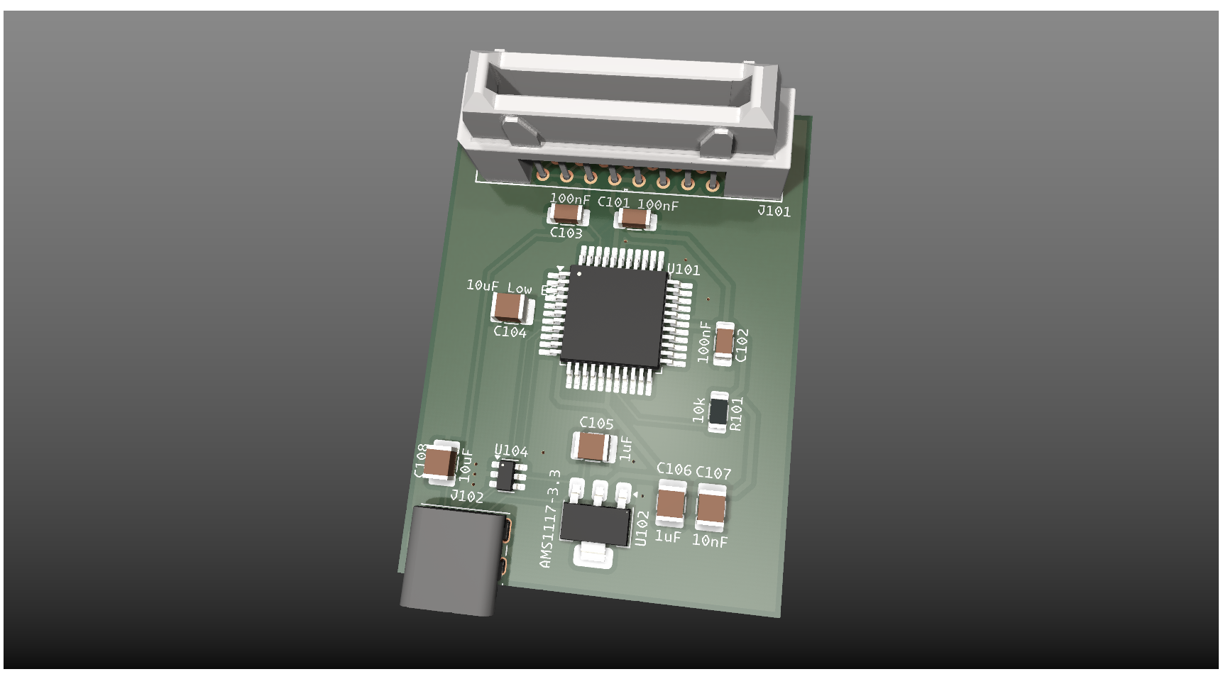
This is the small MCU board that will attach to the larger chessboard
| .gitignore | ||
| chess_mcu_board.kicad_pcb | ||
| chess_mcu_board.kicad_pro | ||
| chess_mcu_board.kicad_sch | ||
| LICENSE | ||
| README.md | ||
FrznChessboard MCU Board
What is it?
This is a separate board that will attach to the main chessboard PCB to control everything. This is being done as a separate PCB for a few reasons:
- To keep the size of the chessboard to a minimum
- To make it easier to route both boards
- To allow a potential wireless device to be properly mounted with no copper pours under it
- The MCU board might end up being a 4-layer board and reducing the size of any 4-layer stuff drastically reduces the overall cost
- Modularity in testing and development - I can potentially make different MCU boards to try different MCUs/modules without having to respin the larget board
Currently the boards will be using a 30-pin board to board interconnect from JAE Electronics -- the TX24/25 pair. This might end up being overkill, but they were actually some of the least expensive interconnects; even less expensive than interconnects with fewer pins!